4.5 INJECTOR DESIGN
The function of an injector, which is located in general, at the forward end of the combustion chamber as shown in figures 4-1 and 4-2, is similar to that of the carburetor of an internal combustion engine. The injector introduces and meters the propellant flow to the combustion chamber, and atomizes and mixes the propellants for satisfactory combustion.
Design Objectives
A great number of injectors have been developed and many details of successful injector designs are now available. However, there still are no hard-and-fast rules to assure a successful design. In the past, most injectors were designed by a trial-and-error approach, with the help of previous test data. While good results have eventually been obtained, it was usually at the expense of large amounts of time and money. A more rational approach toward the design of injectors is through understanding and prediction of the chemical and physical processes that are encountered within the combustion chamber, and using this information as a basis for initial injector design. For a given propellant combination, the chemical reactions and the kinetics of stream breakup, mixing, droplet formation, and heat transfer should be studied and clearly understood, before the approach to the design of an injector is established.
There are numerous requirements to qualify a given injector for operational use. The following are the most important objectives for injector design:
- Combustion stability.-In combination with a given combustion-chamber configuration and for a given propellant combination, an injector should give smooth combustion, during engine start and stop transients as well as during steady-state operation.
Depending upon the propellants and their ignition characteristics, the arrival sequence of oxidizer and fuel streams during start is of great importance. Any accumulation of unburned propellants in the combustion chamber prior to ignition must be prevented to avoid destructive chamber-pressure surges. Similarly, during engine shutoff, chamber overheating and burnout may be prevented by maintaining a fuel-rich mixture. Arrival sequences are best controlled by propellant valve timing. Furthermore, minimum feed-line and injector-manifold volumes between propellant valves and injector face will materially improve propellant sequencing during start and stop.
To prevent chamber-pressure fluctuations from affecting the propellant flows and thus from inducing combustion instability, sufficient pressure drop through injector orifices must be maintained. Effective and even mixing of the propellants will be achieved through the choice of a suitable injector impingement pattern. This will help to minimize accumulation within the combustion chamber of unburned propellants which could cause local detonations and thus trigger combustion instability. Under certain conditions, combustion instabilities of the tangential oscillation mode can be prevented by isolating local detonations by partitioning the injector face into several compartments, as shown in figure 4-40. 2. Performance.-Combustion performance of an injector is influenced by: propellant mass distribution; local mixture ratios; degree of mixing of injected propellants, in either the liquid or the gaseous phase, or both; droplet atomization and vaporization; rate of heat input; and chemical reaction rates. These are predominantly a function of suitable manifolding and proper selection of injector-hole patterns. The more
 Figure 4-40.-Baffled injector.
thorough the mixing and uniform the distribution of the oxidizer relative to the fuel, produced by the injector, the more rapidly will the combustion products reach the equilibrium composition necessary for optimum performance. Although turbulence induced by the combustion probably contributes a major portion of the energy required for gas-phase mixing, thorough premixing of the liquid propellants must be accomplished by the injector if maximum performance is to be achieved. Furthermore, reaction between certain specific propellant combinations such as hypergolic propellants cannot reliably be initiated and maintained without it, since the energy released by liquid-phase reactions supplements the kinetic energy available for the process of atomization through combustion-gas evolution. In addition, the heat release from liquid-phase reaction accelerates the process of vaporization.
Experience has shown that for a given injection velocity, propellant-droplet size is reduced with decreasing injector-orifice size. Smaller droplet size, in turn, results in a higher overall vaporization rate, as a function of increased total droplet surface area. This is true whether the heat of vaporization is supplied internally via liquid phase reaction or externally by heat transfer from the hot gaseous combustion products. Consequently, injector designs with the largest practical number of iniection elements can be expected to be the most efficient ones in a given combustion chamber volume. 3. Structural integrity.-An injector should be able to withstand the maximum loads incurred during all phases of engine operation. Sufficient cooling must be provided to prevent the injector face or any other portion from overheating. 4. Hydraulic qualities -The holes or orifices of the injector must be designed to effect predetermined pressure drops at specific flow rates, and to atomize the propellants properly. A low injector pressure drop is desirable from the standpoint of overall engine-system performance. However, minimum pressure drop is determined from combustion-stability considerations. 5. Combustion chamber heat protection.-An injector should be designed to avoid formation of hot spots or streaks on the combustion chamber wall. Complete mixing of the propellants will prevent oxidizer-rich peak temperature zones from forming, although this may not prevent streaks of high mixture ratio ( ) from occasionally reaching the chamber wall. To offset this, a special set of fuel holes is often provided at the periphery of the injector, close to the chamber wall. Excess fuel along the chamber wall is thus provided which tends to lower the O/F mixture ratio of any errant streak. It also assists in cooling the chamber wall. 6. Special requirements.-Certain engine systems are required to operate at off-nominal conditions, such as at lower thrust levels during throttling, or other than nominal mixture ratios as a result of propellant-utilization control. In these cases, injectors must be capable of operating reliably under modified as well as rated conditions.
Injector Configurations
A typical injector design construction and propellant-distribution method is illustrated in figure 4-2. Different distribution methods are shown in figures 4-41 and 4-42. The injector in figure uses an integral faceplate. This plate is secured to the main injector body by brazing it at the periphery and at posts which are an integral part of the main body. A fuel compartment is located immediately behind the faceplate, and fed from an inlet passage. The oxidizer compartment is separated from the fuel by a partition. The fuel is injected through orifices drilled in the faceplate, while the oxidizer is injected through orifices drilled in the posts.
The injector construction for a typical liquidbipropellant gas generator is illustrated in figure 4-43. The copper injector body is secured to the stainless-steel outer shell by brazing. The oxidizer inlet forms an integral part of the injector body. Fuel is supplied through a manifold in the outer shell. In this injector, 2 fuel streams impinge on each oxidizer stream, producing a total of 44 impingement points.
A variety of injector patterns have been designed to satisfy the needs of various propellant combinations. In most cases, for good mixing the injected streams are made to impinge at a predetermined point. The impingement point should be as close to the injector face as heattransfer conditions permit. The arrangement in which all impinging points are the same distance from the injector face is called uniplanar
 Figure 4-41.-Concentric ring injector.
 Figure 4-42.-Integral face plate injector.
impingement. If two or more different impingingpoint distances are used (fig. 4-44), the arrangement is called biplanar or multiplanar impingement. Numerous tests have been conducted to determine impingement-angle and distance effects. Large included angles will enhance stability, but can result in some of the propellants splashing back on the injector face, which can cause burnouts. Close spacing of the impinging holes in a pair has similar advantages and disadvantages, as has increased spacing between pairs. The satisfactory design value for the included angle is usually found to be between and . The injector face can be further protected against overheating by circulating the propellants on the back side of the faceplate or by introducing film coolant (propellant) on the surface. Some of the impingement patterns used are described below:
- Showerhead (fig. 4-44a).-This pattern em- ploys nonimpinging oxidizer and fuel streams which emerge normal to the injector face. It relies entirely on combustion chamber turbulence for mixing. While being the simplest to fabricate, the showerhead injector exhibits poor performance in most applications, with the exception of certain cryogenic propellant combinations.
- Doublet (fig. 4-44b).-In this design, oxidizer and fuel jets are made to impinge in pairs. Thus good liquid-phase mixing and atomization is obtained. One of the disadvantages of this doublet arrangement is that even if the injector holes have been accurately drilled, the resultant angle of momentum vector, or beta angle, , will vary with mixture ratio, particularly if a large impinging angle is used. This variation can adversely affect combustion performance and chamber-wall heat transfer. The doublet design is frequently used in systems using liquid oxygen.
- Triplet (fig. 4-44c).-Two streams of one propellant impinging symmetrically on one stream of the other propellant will eliminate the change of vector angle , as a result of mixture-ratio variations. This arrangement also provides intimate mixing. Application and propellant combination will determine whether two oxidizer jets will impinge on one fuel jet, or vice versa. Injectors using this triplet pattern have given high combustion performance. These injectors have been widely used for various propellant combinations.
- Quintuplet (fig. 4-44d).-Four streams of one propellant impinging on one stream of the other propellant in a symmetrical quintuplet pattern provide excellent mixing and performance. This design has been applied for various propellant combinations.
- Self-impinging (fig. 4-45a).-This pattern, also known as a like-on-like impingement, generally employs self-impinging pairs of fuel and oxidizer. Mixing is accomplished in the combustion chamber by volatilization of the propellants and by turbulence. This design usually provides good inherent combustion stability, at a moderate performance level. Applications have been successful for both cryogenic and storable hypergolic propellant combinations. A modification of this design provides for secondary impingement of the two propellants following self-impingement.
 Figure 4-43.-Bipropellant gas generator injector.
 Figure 4-44.-Injector impinging patterns.
 Figure 4-45.-Injector impinging patterns.
- Coaxial (fig. 4-45b).-This injector employs two concentric tubes for the two propellants, which are injected coaxially.
- Ring slot (fig. 4-45c).-The ring-slot injector employs concentric pairs of annular slots which eject the propellants as conical sheets. The slots are so arranged that fuel and oxidizer sheets impinge much in the same manner as in the doublet-type injector.
- Splash plates (fig. 4-45d).-This injector is designed for good propellant mixing while the propellants are still in the liquid state. For this purpose, injected propellants are deflected by the splash plates. The plates will be kept cool by the impinging liquid propellants which do not ignite until they have left the plate.
- Premix.-Figure 4-46 shows a typical premix-type injector. Fuel and oxidizer are injected radially into the premixing chamber, where they are intimately mixed before entering the combustion chamber by a gas jet introduced tangentially at the chamber end. The length and diameter of the premixing chamber with relation to the mass flow of propellants is critical, as is the reaction time of the propellants.
- Throttleable injector.-Certain requirements for space vehicle missions, such as orbit corrections, rendezvous and docking maneuvers, and lunar soft landings, demand engine systems capable of thrust control. Figure 4-47a shows a typical throttlable injector with variable injectionslot areas. This is a very effective means of controlling the propellant flows and injector pressure drops at various engine thrust levels. The addition of moving parts, however, causes design complications. Another approach to a throttlable injection system is the "aeration method," as shown in figure 4-47b. An inert gas is introduced into the injector propellant manifold for reduced thrust levels. Through variation of the propellant/gas mixture ratio, the effective density of the propellants can be varied over a wide range to achieve any desired thrust level without affecting combustion stability. The gas can be supplied by the same source used to pressurize the propellant tanks. This method has increased the range of rocket-engine throttling up to a ratio of 100 to 1 .
Design Calculations
For the design of injectors, various parameters, such as injector pressure drop, impingement
[^3]and resultant vector angle relationship, and structural loads, can be calculated with reasonable accuracy. Injection Velocity The propellant (oxidizer or fuel) injection velocity (in/sec) can be calculated from the basic relation:
where is the propellant weight flow rate, is the calculated injector orifice area, in ; and is the propellant density, .
 Figure 4-46.-Premixing type injector.
Injection Pressure Drop The injection pressure drop can be calculated as
where is the gravitational constant, in ; is a dimensionless discharge (velocity and jet contraction) coefficient which is a function of injector orifice configuration.
The value of this coefficient ranges from 0.5 to 0.92 and can be determined accurately by experiment (water flow tests). Injector orifices with well-rounded entrance and smooth bore give high values of the discharge coefficient. For a given injection velocity, a higher value of discharge coefficient gives a lower injection pressure drop. The rule-of-thumb design value for injector pressure drop varies from 15 to 20 percent of the chamber-nozzle stagnation pressure. Resultant Angle of Impinging Streams The angle between the thrust chamber axis and the resultant momentum vector of a pair of impinging streams is defined as the beta angle, . By definition when the vector is directed toward the chamber wall, the beta angle is positive, and when the vector is directed toward the
 Figure 4-47.-Throttleable injecting methods.
central axis of the thrust chamber, the beta angle is negative. With a hypergolic-type propellant combination, a positive beta angle ( to ) tends to increase the combustion performance by causing recirculation and better mixing of the liquid propellants along the chamber wall. However, in a cryogenic propellant combination. where gaseous mixing is predominant, the combustion performance will not be noticeably affected by the beta angle. A negative beta angle should be used in this case to avoid the possibility of hot streaks on the chamber wall caused by excessive heat transfer.
The beta angle may be readily calculated, from the principle of conservation of momentum:
For the impinging streams shown in figure 4-48, and are the respective angles between the thrust chamber axis and the streams; and are the weight flow rates; and and are the injection velocities.
Injection Momentum Ratio
The injection momentum ratio can be defined by the expression
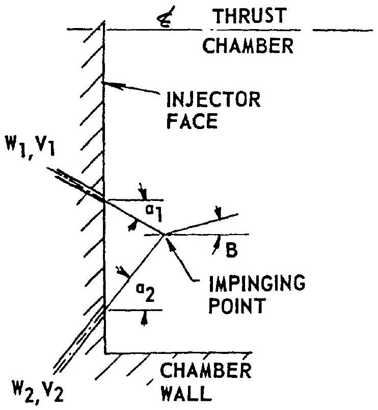 Figure 4-48.-Resultant angle of impinging streams.
where and are weight flow rates, and and are injection velocities for oxidizer and fuel. The injection momentum ratio is a useful injector design parameter for the prediction of combustion stability and performance of certain propellant combinations. In the design of oxygenhydrogen injectors, the value of the momentum ratio varies from 1.5 to 3.5 for liquid hydrogen injection, and from 0.5 to 0.9 for gaseous hydrogen injection.
Structural Loads
The main loads to be considered in the structural design of injectors result from propellant pressures behind the injector face, and in the manifolds. During steady-state main-stage operation, the pressure load on the injector face is equal to the injector pressure drop:
The pressure load in the injector manifolds is equal to the sum of the injector-end chamber pressure and the injector pressure drop:
where is the pressure load on the injector face, is the pressure load in the manifold; is the injector pressure drop; and is the injector-end chamber pressure.
During start transients, however, maximum pressure loads on the injector may be substantially higher than during steady state. When the propellant valves are opened rapidly, propellants rushing into the empty injector passages can cause severe hydraulic ram. This pressure load can be estimated empirically as
where is the propellant pressure at time of valve opening.
Sample Calculation (4-8)
Using data given in tables 3-2 and 3-3, determine the injector orifice sizes, injection velocities and momentum ratios for the A-1 and A-2 engines.
Solution
(a) A-1 Engine
Thrust chamber propellant flow rates are 1941 (oxidizer) and (fuel); propellant densities are (oxidizer) and (fuel); injector pressure drops are 200 psi for both propellants. Based on component test results an injector orifice discharge coefficient of 0.75 is used for both sides. Substituting it into equation (4-40), and converting feet to inches:
For the oxidizer side:
Total oxidizer injector orifice area: For the fuel side:
Total fuel injector orifice area: An injector pattern of 700 pairs of selfimpinging streams is used for both oxidizer and fuel. The following orifice areas and diameters result:
From equation (4-39), and using orifice areas obtained above for available and , mean injection velocities are determined:
For the oxidizer: or For the fuel: or
In support of the injector development engineer, who may wish to compare with earlier test data, the injection momentum ratio is determined, using equation (4-42):
(b) A-2 Engine
From table 3-3, the propellant flow rates for the thrust chamber are (oxidizer) and (fuel); the propellant densities are (oxidizer) and (fuel; gaseous hydrogen at ); the injector pressure drops are 160 psi (oxidizer) and 60 psi (fuel). With the coaxial injecting pattern (fig. 4-45b), experimental tests give a value of 0.62 for the oxidizer-side discharge coefficient and a value of 0.9 for the fuel side. Substitute these into equation (4-40). For the oxidizer side:
Total injector oxidizer orifice area: For the fuel side:
Total injector fuel orifice area: Use a total of 300 coaxial elements for the injector. The individual orifice areas and diameters will be
Use a tube inner wall thickness of 0.025 inch. The diameters for the annular fuel orifice will be
From equation (4-39), the injecting velocities are
For the oxidizer: or For the fuel: or
From equation (4-42), the injection momentum ratio
Experimental Evaluation of Injector Designs
The design of an injector can be improved through experimental testing. Three types of tests are usually employed: hydrostatic pressure, water flow, and hot firing. The hydrostatic pressure tests are used to determine whether the injector structure will withstand the required pressure loads. The water flow tests are used to evaluate the following design characteristics:
- Effective injector pressure drop.-The data from the water-flow tests can be used to determine the orifice-discharge coefficient and to predict the injector pressure drop for the design propellant, with corrections for density and viscosity.
- Injection pattern.-Injection pattern and impingement can be observed, and faulty operation can be detected and corrected.
- Atomization.-Water-flow tests at velocities corresponding to those employed in actual service indicate the quality of atomization to be expected with the actual propellants.
The true injector operational characteristics, such as performance, combustion stability, and heat-transfer characteristics for main-stage conditions, as well as start-and-stop transients, can only be fully evaluated by hot firing tests, in a thrust chamber of representative design or a "workhorse" equivalent.
It is often beneficial if during the hot-firing tests of a given injector configuration, certain operational parameters such as injector pressure drops, thrust chamber shape, and can be changed to determine the effects on performance and stability. In such an experimental evaluation program injector, orifice hole patterns can be redrilled or holes plugged, until an optimum configuration is obtained.
Heat-transfer characteristics are an important factor when evaluating an injector design. Temperature-measuring instruments embedded in chamber walls and injector face are required to measure heat-transfer rates and to detect local hot spots. Instrumentation for measuring propellant flows, chamber pressure, and combustion vibration characteristics are similarly important for determining the true levels of injector performance and stability.